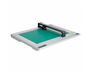
Graftec's FC2250 Large Format flatbed cutting plotter has an (optional) electrostatic holdown cutting surface.
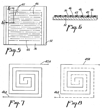
The holdown surface is basically an electrode grid, where the + and - are "intermeshed" or "interdigitated", so they don't touch, and an electric charge builds up in the material that separates them. Like this, for example:
And it has a plastic top coating.
US Patent 3,634,740 says:
The top coating is a white opaque plastic. It must be opaque to hide the electrode grid, and white because it is used as a photographic copyboard. This is an application limitation and not necessary to the functioning of the board. If the board were used as a wall hanging bulletin board, then any color, or even a clear plastic covering would suffice. Another practical limitation is that the top coating be at least l0 mils (10 thou) thick. This limitation is to keep any operator who might come in contact with the surface of the board while it is in operation from getting a shock. If there is no problem of personal contact, then the top coating may be made thinner and will permit greater holding power. Conversely, a thicker top coating will give less holding power. The most important property of the top coating is that its bulk resistivity be 15 ohm-centimeters or less. For this top coating, such plastics as flexible polyvinylchloride, polyvinylfluoride, and glass reinforced melamine have been used. Top coatings can be of multilayer design also, to obtain certain surface properties. For example, color, opaqueness, cleanability, wear resistance, and to protect indicia lines are reasons for making composite surfaces.
I bolded flexible polyvinylchloride because I was so happy to see it on the list. This drawing from Alvin, maker of self-healing cutting mats shows the lamination that makes up their mats:
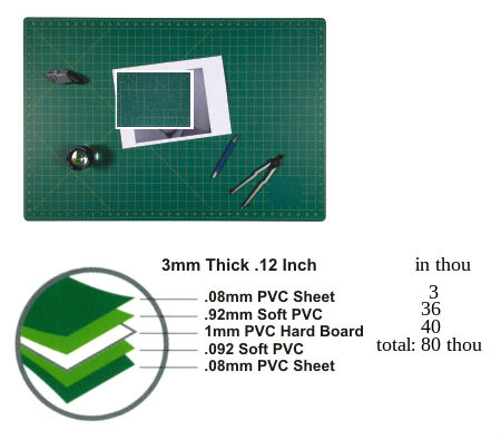
I totalled up only the first 3 layers because the mats are symetrical, and a cutting tool, I imagine, stops at the hardboard layer. I put the mm dimensions in terms of thou to be easily comparable to the quote from the patent. It's great that flexible PVC is potentially a suitable material, but it's potentially way too thick. One source I consulted said that the holding power decreases as the inverse-squared of the coating's thickness, so an 8x thicker coating would have 1/64th of the holding power. Ouch.
It would be possible to use a router thicknessing jig to "plane" a cutting mat to different thicknesses, and compare their holding powers. Better though, would probably be to source PVC sheet, instead of modifying an existing cutting mat.

You will like this part of the patent, about how to apply the electrode grid to the top surface:
These electrodes are spaced so that an electric potential may be applied between them, generating an electrostatic field. The electrodes are in the form of interdigitated fingers about three-fourths inch wide, connected by header bars with the normal spacing between the fingers of the electrodes about three-sixteenths of an inch. The grid, or electrode pattern, may be mounted on the base in many ways. The standard printed circuit technique of etching conductors in copper-clad material, or silk screening a conductive ink onto a base material, or hot stamping, are other standard methods that can be used. The electrodes may also be formed from metal foil, wires, conductive inks, or even pencil lines. They may be applied by printing, silk screening lithography, etching, electroplating, or drawing. Those versed in the arts of lithography, silk screening, printed circuits, and printing will immediately see many ways of producing the electrodes. The term conductor or conductive ink or paint used in this description includes resistive conductors, inks or paints. This is true because the current needed to cause the holddown board to operate satisfactorily is so very small that materials normally considered as being resistive or even insulating will actually carry enough current to make the board operate satisfactorily. (it is a high voltage, low current device) The top coating and the base material may be joined in many ways. Examples are by laminating, heat sealing, ultrasonic welding, gluing or adhesives. The top coating may also be merely laid on top of the base material and will still operate as a holddown. If an adhesive or glue is used, this material must be about the same bulk resistivity as the top coating. If it has a high resistivity and gets between the electrodes and the top coating, then no current will flow through the top coating, and no holddown will occur.
So it seems like a good place to start would be to make a silkscreen with the electode pattern, then get a variety of sheets of PVC (rigid, flexible, different thicknesses) and silkscreen the same pattern on the different sheets, and see which works best. Obviously it's also important to source the right kind of power supply. And hopefully a successfull small scale text (12" x 12", say) would translate to a large (40" x 60", say) size and work the same.
If it really is possible to silkscreen conductive ink onto an (especially thin) cutting at, and then attach that to a power supply, and have paper stick to it, that would be a very elegant solution. I hope that is in fact possible.
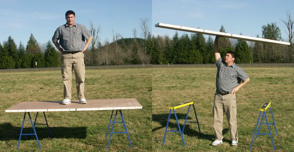
If a honeycomb panel like the above, from Singcore, is a suitably flat and rigid surface for a plotter/cutter, then a panel like this + an electroadhesive cutting mat, I think that's an elegant solution to large-format holddown, less fuss than a vacuum table.
About the power supply:
The electrostatic holding action is created by applying an electrical potential between the electrodes of from 1,000 to 4,000 volts. A voltage multiplier is used. Voltage multipliers are well known. The fact that a very small amount of current is consumed, enables the practical use of a voltage multiplier of inexpensive proportions. The exact voltage potential will be determined by electrode spacing and the top coating resistivity.
About the width of the electrode fingers:
The theoretical predictions have been conferred in experimental study. It has been proven that thick art materials may be held. The holding power increases with the increase in finger width, because the flux pattern is provided in a high arc over the gap from the extreme edges of the fingers. So, for composing original work by assembly of sheet material overlapping one another, wide electrodes are preferred. But very small pieces which do not bridge over two or more fingers and a gap, may not develop enough holding power.